Search This Blog

Friday 25 August 2023


TO MIRROR ARMATURE BONES ON X AXIS


1. Assume that we are making a human rig in standing position.
2. Set the view to front view.
3. Create the armature with the center bones along the z axis and the hand and leg bones on the positive side of the x axis.
4.Select the head of the root bone. Position 3D cursor at the head of the root bone pressing Shift+S >"Cursor to selected". Next change the pivot point to 3D cursor.
5. To mirror the bones on the Positive side of x axis to the negative side of x axis, select all bones on positive side of x axis,taking care not to select the central bones. Press Shift+D to duplicate, then Ctrl+m, x , -1 to mirror on the x axis.
6. Alternately, after duplicating the bones, press s, x -1 to mirror on the x axis.

Monday 26 September 2022

DELTA TRANSFORMS

  Delta Transforms are  transformations that are applied on top of the normal transforms applied using location, rotation and scale transform. Delta Transforms are particularly useful in animations. For example, you can animate an object with the primary transforms then move them around with Delta Transforms.

 As an example, we can animate a cube to move from point A to B.
Let the the initial position(A) be 0,0,0. Set a key frame at frame no 1. Set End frame as 100, move the Timeline cursor to frame 100.Move the Cube to position (B) at 10,0,0 and set a key frame here. When we run the animation,the Cube will move from A to B.

  Now after setting the key frames, if we drag the Cube to position 3,0,0 and then  play the animation, the Cube will once again jump back to position A and move to position B. From 000 to 10,0,0.

 Reset the Cube to position 0,0,0 and save file.

 Now we shall look at Delta Transforms. Delta is a term adapted from Maths, where it means a small change in the existing value of a variable.  

 In the properties window, open the Object Data tab and click on Delta Transform panel. Here we can set the Delta value for Location, Rotation and Scale Transformation.
 
Set the Delta Location value to 4,0,0.  

 Now play the animation. The Cube will start from position 4,0,0 and go upto 14,0,0.

 What we have effectively done is retained the basic animation of the Cube, but shifted the starting point to 4,0,0 and End point to 14,0,0.

 As another example , to understand the use of Delta Transforms, reset Delta Location Value to 0,0,0 and set Delta Rotation value as 45,0,0.

 Now play the animation. The Cube would be rotated by 45 degrees on X axis and move from 0,0,0 to 10,0,0.

 Similarly, if we set the Delta Scale value to 2,2,2 and play the animation, the Cube will move from 0,0,0 t0 10,0,0 with both these additional Delta transforms.

 The next question which arises, is where do I use this Delta Transforms? We shall adddress this query now.

We shall list out a few example cases.

1. Animate a car object to move from A to B. Duplicate the car object and set its Delta Location to position it away from the location of the first object.Animate them. Now both cars will move simultaneously. If you want multiple objects to execute the same animation, this technique can be used.

2. Image a human object standing, facing you. When animated,this object will turn left by 90 degrees.Suppose we duplicate this object, 80 times and make them stand in 8 columns, with 10 object in each column.  When we play the animation, all 80 object will turn left simultaneously. Image how tedious it would be to set key frame for each of the 80 objects to execute this rotation transform !  

3. Let us say, we have 10 ceiling fans in a hall,  turned on. We want to animate all the 10 fans. Delta Transforms can be used here.

4.   Let us say we have 10 Dish Antenna. If we want all 10 to rotate in the same manner, Delta Transform can be used.

5. In a stage set up, suppose we want 10 lamps to swing in  the same manner, we can do use Delta transforms.

Another way we can use delta transforms is to use them directly. An example will clarify this method.

 Select a Cube located at 0,0,0. In the properties panel, set the Delta location value to 5,0,0.Set Timeline cursor at frame 1 in Timeline Editor window.  With the Cube selected in the 3D window, press I to open up the "Insert Key frame Menu" and click on  Delta Location. A key frame will be inserted at Frame 1. Move the Timeline cursor to from 100, which we set as the end frame number, for Delta Location value enter 15,0,0. Select Cube in 3D window and press I and then click on Delta Location to insert a key frame at frame 100. Save file and play animation. The Cube Will move from 5,0,0 to 15,0,0 location.

 If we duplicate the Cube and position them at different X locations, play animation, all the Cube will move 10 units. This way we can animate multiple objects by setting key frames for a single object and making duplicates of the Cube and positioning them at different points.

 Demonstration of the Delta Transforms is shown in the video link given below:

Delta Transforms 

Link to some animations, done using Delta Transforms:

Fighter Jets

Cars 


Tuesday 6 September 2022

ANIMATION IN BLENDER 2.79


 ANIMATION PART 1 -NOTES

INTRODUCTION - BASIC CONCEPT OF ANIMATION.

Animation is the process of making something appear to move  by showing a series of still images, one after another, each one slightly different from the previous one, creating an  illusion of motion. This is the concept used in movies. When the images are moved at a rapid speed of 24 pictures(frames) per second or more, then the human brain perceives such change as continuous, which is based on the concept of "Persistence of vision".

TECHNICAL DETAILS

FRAMES, FRAMES PER SECOND, DIFFERENT VIDEO STDS –NTSC,PAL ETC.


Each image in animation is called a frame. Normally 24 frames are shown per second (fps). In Blender we set up scenes using the different characters called object, which perform some action. To enhance the quality of the scene, colored back ground, lighting are included. The whole action is displayed on the computer screen. This is captured by the camera, set up inside Blender and converted into still images which when assembled sequentially becomes a video.
A series of videos assembled with proper sound effects becomes a movie. For display on television the American Standard NTSC specifies 30 fps and the Australian Standard PAL follows 25 fps.
A one minute video, will have 60X24=1440 frames, for 24 fps.


TIMELINE EDITOR.


Time line editor is basically used to set and visualize the frame movement, with its control to start, stop and rewind buttons and provision for setting the total number of frames. It is used for setting the key frames.

 PART 1

OBJECTIVE : BASIC ANIMATION -TO MOVE AN OBJECT FROM POINT A TO POINT B AND THEN TO POINT A.

STEPS

1.ADD AN OBJECT TO ANIMATE.


2.SET FRAME RATE AS 24 FPS, TOTAL NO OF KEY FRAMES 240. START FRAME IS 1 AND END FRAME IS 240.

3.SET KEY FRAME FOR THE OBJECT AT POINTS A, B AND  A AGAIN. SAVE FILE.


4. PLAY ANIMATION.

STEP 1 :ADD AN OBJECT TO ANIMATE

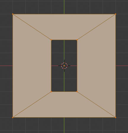
To add an object in 3D window, set your cursor in the 3D window and then press Shift+A keys. A pop-up menu will appear. Here select "Mesh" and then "Cube". A Cube will be added at the location where the cursor was last positioned.

Set the view to Front Ortho view, by pressing "1" and then "5", in the Numpad.

To see the x, y, z location coordinates of the cube,  press "N" key while the cursor is still in the 3D window. A  properties panel will appear on the right side where you should be able to see the location coordinates of the Cube. Set it to x=0,y=0, z=0. Let us assume that this will be point A where the Cube shall be located in  our animation.


STEP 2 : SET START AND END KEY FRAMES


The Start and End key frames are set to 1 and 240 by default. The frame Rate per second(fps) is set to 24fps, the default value.


STEP 3:SET KEY FRAMES

Key frames, are set in the 3d Window, key frame is visible in the Time line window. The current location of the cursor, indicated by the vertical green line in the Time line window is the frame number which we want to set as key frame. When a frame is set as key-frame, a small, vertical yellow line will appear along with the green line in the TimeLine Window.

To set a key-frame, SELECT the Cube, by clicking the Right Mouse Button(RMB) on the Cube. An yellow border-line will appear around the Cube. (If you want to deselect the cube,press "A" key). Let the Cube remain be selected. Note that the current location of the Cube is 0,0,0.

To SET KEY FRAME, press  the "I" button and then click on "Location", in the pop-up menu.A key frame is set  for this location of the Cube. This is indicated by the small yellow line, in the Time Line Window.

Save the File, by pressing Ctrl+S. In Blender, you need to save the file, frequently at regular intervals, to save your work.  

Now we need to repeat these steps for the two other location of the Cube at Point B and C.

Now we shall set key frame for point B.
In the Timeline Window, click on the green line using your Left Mouse Button(LMB) and drag it to frame number 120.This value is displayed on  the Current Frame Number button in the Time Line Window. We  can set the Current frame also by entering a value here. This is an alternate method to set current key frame.

Let us position the Cube at x=0,y=0,z=5, by entering these values  for location in the properties panel.

Make sure the Cube is selected, indicated by the yellow border line around the Cube. Click on "I" Button. Select "Location" in the pop-up menu. A small yellow line will be displayed at frame number 80, in the Timeline Window.

Save the File, by pressing Ctrl+S.


In the Timeline Window, click on the green line using your Left Mouse Button(LMB) and drag it to frame number 240.This value is displayed on  the Current Frame Number button in the Time Line Window. We  can set the Current frame by entering a value here. THis is an alternate method to set current key frame.

Let us position the Cube at x=0,y=0,z=0, by entering these values  for location in the properties panel.

Make sure the Cube is selected, indicated by the yellow border line around the Cube. Click on "I" Button. Select "Location" in the pop-up menu.

Save the File.


At this stage, four yellow lines must be displayed in the TimeLine Window at frame 1,120 and 240.In case you want to delete a key frame, select the key frame,with the Cursor positioned within the 3D window, press "Alt+I" key. Save the File.


STEP 4: PLAY ANIMATION

First set the current frame to frame 1 in the Timeline Window. Press Alt+A keys to play the Animation. The Cube must move from location A to B to C  and repeat the cycle.You can also press the > key, which is the play button in the Timeline Window. To stop the animation, press on the Play Button once more, or hit the "Esc" key.

This completes Part 1. Though the instruction may seem to be elaborate, it is meant to assist the first time learner. Once you get a hang of the steps, it is hardly a few minutes job.

Just play around. If some thing goes wrong, badly, start over again ! Nothing to loose.
 
 VIDEO LINK :ANIMATION USING BLENDER 2.79 PART 1 


VIDEO LINK : ANIMATION USING BLENDER 2.79 PART 2


VIDEO LINK : ANIMATION USING BLENDER 2.79 PART 3


VIDEO LINK : ANIMATION USING BLENDER 2.79 PART 4


VIDEO LINK: ANIMATION USING BLENDER 2.79 PART 5 


Thursday 30 December 2021

SINE WAVES-RED,YELLOW AND BLUE SCRIPT

#THIS SCRIPT WORKS WITH BLENDER 2.8 AND ABOVE.

 import bpy
from math import sin,cos,pi

radius=100
deg=2*pi

#TO DELETE ALL EXISTING OBJECTS
bpy.ops.object.mode_set(mode='OBJECT')
bpy.ops.object.select_by_type(type='MESH')
bpy.ops.object.delete(use_global=False)


for t in range (0,360):
    
    #RED
    z=radius*sin(t*deg/360)
    x=t
    y=0
    bpy.ops.mesh.primitive_cube_add(location=(x,y,z))
    bpy.ops.transform.resize(value=(0.9,0.9,0.9))
    obj_matl=bpy.data.materials.new("obj_clr")
    obj_matl.diffuse_color=(1,0,0,1)
    mesh=bpy.context.object.data
    mesh.materials.clear()
    mesh.materials.append(obj_matl)
    #YELLOW
    z=radius*sin(t*deg/360)
    x=t+120
    y=0
    bpy.ops.mesh.primitive_cube_add(location=(x,y,z))
    bpy.ops.transform.resize(value=(0.9,0.9,0.9))
    obj_matl=bpy.data.materials.new("obj_clr")
    obj_matl.diffuse_color=(1,0.6,0,1)
    mesh=bpy.context.object.data
    mesh.materials.clear()
    mesh.materials.append(obj_matl)
    #BLUE
    z=radius*sin(t*deg/360)
    x=t+240
    y=0
    bpy.ops.mesh.primitive_cube_add(location=(x,y,z))
    bpy.ops.transform.resize(value=(0.9,0.9,0.9))
    obj_matl=bpy.data.materials.new("obj_clr")
    obj_matl.diffuse_color=(0,0,1,1)
    mesh=bpy.context.object.data
    mesh.materials.clear()
    mesh.materials.append(obj_matl)

The wave form generated by the script can be seen by clicking on the link given  below:

SINE WAVE LINK 


Sunday 26 December 2021

BPY SCRIPT TO ADD 50 CUBES AND ANIMATE THEM

In this script we add 50 cubes at random location, set random color to each cube and set key frames to each cube to animate them.

The number of cubes added can be changed by setting the range value in the first for loop.Total number of frames is set in the beginning by setting the value for the variable total_frames. Key frame interval is adjusted by setting the third variable in the range setting of the second for loop.Here it is set to 10. The diffuse color setting has four values for Red, Green, Blue and Alpha.

import bpy
from math import sin, pi
from random import randint

total_frames=100

# clear meshes in the scene
for obj in bpy.data.objects:
    if obj.type == 'MESH':
        bpy.data.objects.remove(obj)

#CREATE 10 CUBES        
for i in range (50):
    x=randint(-10,10)
    y=randint(-10,10)
    z=randint(-10,10)    
    bpy.ops.mesh.primitive_cube_add( location=(x,y,z))
    cube=bpy.context.object
    # TO ADD NEW MATERIAL TO EACH CUBE
    matl=bpy.data.materials.new("mat_clr")
    matl.diffuse_color = (x*0.6,y*0.3,z*0.1,1)
    mesh=cube.data
    mesh.materials.clear()
    mesh.materials.append(matl)
    
    # SET KEYFRAMES FOR EACH CUBE
    for frame in range(0, total_frames,10):
        bpy.context.scene.frame_set(frame)
        x=randint(-10,10)
        y=randint(-10,10)
        z=randint(-10,10)

        cube.location=(x,y,z)
        cube.keyframe_insert(data_path='location')


A link to the rendered video file is given below:

https://drive.google.com/file/d/1ZSFBqbky9fEUKng0ZanPFgLFlcWgkLO1/view?usp=sharing


Tuesday 21 December 2021

BPY SCRIPT TO ADD MULTIPLE CUBES IN CIRCLES

This script adds multiple Cubes in concentric circles

-----------------------------------------------------------------------------------------------------------------------------
import bpy
import csv
from math import sin,cos,pi

d =pi/180 # FORMULA TO CHANGE RADIAN TO DEGREE
i=0 #  LOOP COUNTER


radius=4*1.1
x=0
y=0
z=0


for i in range (12):
  x=radius*sin(30*i*d)
  y=0
  z=radius*cos(30*i*d)
  bpy.ops.mesh.primitive_cube_add(radius=1, view_align=False, enter_editmode=False, location=(x,y,z))
 
radius+=5

for i in range (24):
  x=radius*sin(15*i*d)
  y=0
  z=radius*cos(15*i*d)
  bpy.ops.mesh.primitive_cube_add(radius=1, view_align=False, enter_editmode=False, location=(x,y,z))
radius+=5

for i in range (48):
  x=radius*sin(7.5*i*d)
  y=0
  z=radius*cos(7.5*i*d)
  bpy.ops.mesh.primitive_cube_add(radius=1, view_align=False, enter_editmode=False, location=(x,y,z))
radius+=5

for i in range (96):
  x=radius*sin(3.75*i*d)
  y=0
  z=radius*cos(3.75*i*d)
  bpy.ops.mesh.primitive_cube_add(radius=1, view_align=False, enter_editmode=False, location=(x,y,z))
radius+=5

-----------------------------------------------------------------------------------------------------------------------------


BPY SCRIPT TO ADD MULTIPLE CUBES

This script must have a cube object to start with. This object is duplicated and assigned random material.

-------------------------------------------------------------------------------------------------------------------------------------------------------
import bpy
from random import randint
import random

number=100


#TO DELETE ALL EXISTING OBJECTS

bpy.ops.object.select_by_type(type='MESH')
bpy.ops.object.delete(use_global=False)

#TO ADD CAMERA
bpy.ops.object.camera_add(view_align=True, location=(0,-45,0), rotation=(1.5708,0,0))
bpy.ops.transform.resize(value=(9.42627, 9.42627, 9.42627))


#TO ADD BG PLANE
bpy.ops.mesh.primitive_plane_add( location=(0,10,0))
bpy.ops.transform.resize(value=(10, 10, 10))
bpy.ops.transform.rotate(value=-1.55203, axis=(-1, 0,0))
bpy.ops.transform.resize(value=(2,2,2))

#TO ADD MATERIAL TO PLANE
obj_matl=bpy.data.materials.new("obj_clr")
obj_matl.diffuse_color=(0,0.9,0.8)
mesh=bpy.context.object.data
mesh.materials.clear()
mesh.materials.append(obj_matl)

#TO CREATE MULTIPLE TORUS AND ASSIGN MATERIAL
for i in range(0,number):
    x=randint(-10,10)
    y=randint(-5,5)
    z=randint(-10,10)
    p=randint(1,10)
    bpy.ops.mesh.primitive_cube_add(location=(x,y,z))
    bpy.ops.transform.resize(value=(p*0.1,p*0.1,p*0.1))
    bpy.ops.transform.rotate(value=1.5708, axis=(1, 1, 0))
    p=randint(0,9)
    #print(p)
    obj_matl=bpy.data.materials.new("obj_clr")
    obj_matl.diffuse_color=(0.8,p*0.3,0)
    mesh=bpy.context.object.data
    mesh.materials.clear()
    mesh.materials.append(obj_matl)

--------------------------------------------------------------------------------------------------------------------------------

TO MIRROR ARMATURE BONES ON X AXIS 1. Assume that we are making a human rig in standing position. 2. Set the view to front view. 3. Create t...