Search This Blog

Showing posts with label Blender. Show all posts

Monday, 26 September 2022

DELTA TRANSFORMS

  Delta Transforms are  transformations that are applied on top of the normal transforms applied using location, rotation and scale transform. Delta Transforms are particularly useful in animations. For example, you can animate an object with the primary transforms then move them around with Delta Transforms.

 As an example, we can animate a cube to move from point A to B.
Let the the initial position(A) be 0,0,0. Set a key frame at frame no 1. Set End frame as 100, move the Timeline cursor to frame 100.Move the Cube to position (B) at 10,0,0 and set a key frame here. When we run the animation,the Cube will move from A to B.

  Now after setting the key frames, if we drag the Cube to position 3,0,0 and then  play the animation, the Cube will once again jump back to position A and move to position B. From 000 to 10,0,0.

 Reset the Cube to position 0,0,0 and save file.

 Now we shall look at Delta Transforms. Delta is a term adapted from Maths, where it means a small change in the existing value of a variable.  

 In the properties window, open the Object Data tab and click on Delta Transform panel. Here we can set the Delta value for Location, Rotation and Scale Transformation.
 
Set the Delta Location value to 4,0,0.  

 Now play the animation. The Cube will start from position 4,0,0 and go upto 14,0,0.

 What we have effectively done is retained the basic animation of the Cube, but shifted the starting point to 4,0,0 and End point to 14,0,0.

 As another example , to understand the use of Delta Transforms, reset Delta Location Value to 0,0,0 and set Delta Rotation value as 45,0,0.

 Now play the animation. The Cube would be rotated by 45 degrees on X axis and move from 0,0,0 to 10,0,0.

 Similarly, if we set the Delta Scale value to 2,2,2 and play the animation, the Cube will move from 0,0,0 t0 10,0,0 with both these additional Delta transforms.

 The next question which arises, is where do I use this Delta Transforms? We shall adddress this query now.

We shall list out a few example cases.

1. Animate a car object to move from A to B. Duplicate the car object and set its Delta Location to position it away from the location of the first object.Animate them. Now both cars will move simultaneously. If you want multiple objects to execute the same animation, this technique can be used.

2. Image a human object standing, facing you. When animated,this object will turn left by 90 degrees.Suppose we duplicate this object, 80 times and make them stand in 8 columns, with 10 object in each column.  When we play the animation, all 80 object will turn left simultaneously. Image how tedious it would be to set key frame for each of the 80 objects to execute this rotation transform !  

3. Let us say, we have 10 ceiling fans in a hall,  turned on. We want to animate all the 10 fans. Delta Transforms can be used here.

4.   Let us say we have 10 Dish Antenna. If we want all 10 to rotate in the same manner, Delta Transform can be used.

5. In a stage set up, suppose we want 10 lamps to swing in  the same manner, we can do use Delta transforms.

Another way we can use delta transforms is to use them directly. An example will clarify this method.

 Select a Cube located at 0,0,0. In the properties panel, set the Delta location value to 5,0,0.Set Timeline cursor at frame 1 in Timeline Editor window.  With the Cube selected in the 3D window, press I to open up the "Insert Key frame Menu" and click on  Delta Location. A key frame will be inserted at Frame 1. Move the Timeline cursor to from 100, which we set as the end frame number, for Delta Location value enter 15,0,0. Select Cube in 3D window and press I and then click on Delta Location to insert a key frame at frame 100. Save file and play animation. The Cube Will move from 5,0,0 to 15,0,0 location.

 If we duplicate the Cube and position them at different X locations, play animation, all the Cube will move 10 units. This way we can animate multiple objects by setting key frames for a single object and making duplicates of the Cube and positioning them at different points.

 Demonstration of the Delta Transforms is shown in the video link given below:

Delta Transforms 

Link to some animations, done using Delta Transforms:

Fighter Jets

Cars 


Thursday, 30 December 2021

SINE WAVES-RED,YELLOW AND BLUE SCRIPT

#THIS SCRIPT WORKS WITH BLENDER 2.8 AND ABOVE.

 import bpy
from math import sin,cos,pi

radius=100
deg=2*pi

#TO DELETE ALL EXISTING OBJECTS
bpy.ops.object.mode_set(mode='OBJECT')
bpy.ops.object.select_by_type(type='MESH')
bpy.ops.object.delete(use_global=False)


for t in range (0,360):
    
    #RED
    z=radius*sin(t*deg/360)
    x=t
    y=0
    bpy.ops.mesh.primitive_cube_add(location=(x,y,z))
    bpy.ops.transform.resize(value=(0.9,0.9,0.9))
    obj_matl=bpy.data.materials.new("obj_clr")
    obj_matl.diffuse_color=(1,0,0,1)
    mesh=bpy.context.object.data
    mesh.materials.clear()
    mesh.materials.append(obj_matl)
    #YELLOW
    z=radius*sin(t*deg/360)
    x=t+120
    y=0
    bpy.ops.mesh.primitive_cube_add(location=(x,y,z))
    bpy.ops.transform.resize(value=(0.9,0.9,0.9))
    obj_matl=bpy.data.materials.new("obj_clr")
    obj_matl.diffuse_color=(1,0.6,0,1)
    mesh=bpy.context.object.data
    mesh.materials.clear()
    mesh.materials.append(obj_matl)
    #BLUE
    z=radius*sin(t*deg/360)
    x=t+240
    y=0
    bpy.ops.mesh.primitive_cube_add(location=(x,y,z))
    bpy.ops.transform.resize(value=(0.9,0.9,0.9))
    obj_matl=bpy.data.materials.new("obj_clr")
    obj_matl.diffuse_color=(0,0,1,1)
    mesh=bpy.context.object.data
    mesh.materials.clear()
    mesh.materials.append(obj_matl)

The wave form generated by the script can be seen by clicking on the link given  below:

SINE WAVE LINK 


Sunday, 26 December 2021

BPY SCRIPT TO ADD 50 CUBES AND ANIMATE THEM

In this script we add 50 cubes at random location, set random color to each cube and set key frames to each cube to animate them.

The number of cubes added can be changed by setting the range value in the first for loop.Total number of frames is set in the beginning by setting the value for the variable total_frames. Key frame interval is adjusted by setting the third variable in the range setting of the second for loop.Here it is set to 10. The diffuse color setting has four values for Red, Green, Blue and Alpha.

import bpy
from math import sin, pi
from random import randint

total_frames=100

# clear meshes in the scene
for obj in bpy.data.objects:
    if obj.type == 'MESH':
        bpy.data.objects.remove(obj)

#CREATE 10 CUBES        
for i in range (50):
    x=randint(-10,10)
    y=randint(-10,10)
    z=randint(-10,10)    
    bpy.ops.mesh.primitive_cube_add( location=(x,y,z))
    cube=bpy.context.object
    # TO ADD NEW MATERIAL TO EACH CUBE
    matl=bpy.data.materials.new("mat_clr")
    matl.diffuse_color = (x*0.6,y*0.3,z*0.1,1)
    mesh=cube.data
    mesh.materials.clear()
    mesh.materials.append(matl)
    
    # SET KEYFRAMES FOR EACH CUBE
    for frame in range(0, total_frames,10):
        bpy.context.scene.frame_set(frame)
        x=randint(-10,10)
        y=randint(-10,10)
        z=randint(-10,10)

        cube.location=(x,y,z)
        cube.keyframe_insert(data_path='location')


A link to the rendered video file is given below:

https://drive.google.com/file/d/1ZSFBqbky9fEUKng0ZanPFgLFlcWgkLO1/view?usp=sharing


Tuesday, 21 December 2021

BPY SCRIPT TO ADD MULTIPLE CUBES IN CIRCLES

This script adds multiple Cubes in concentric circles

-----------------------------------------------------------------------------------------------------------------------------
import bpy
import csv
from math import sin,cos,pi

d =pi/180 # FORMULA TO CHANGE RADIAN TO DEGREE
i=0 #  LOOP COUNTER


radius=4*1.1
x=0
y=0
z=0


for i in range (12):
  x=radius*sin(30*i*d)
  y=0
  z=radius*cos(30*i*d)
  bpy.ops.mesh.primitive_cube_add(radius=1, view_align=False, enter_editmode=False, location=(x,y,z))
 
radius+=5

for i in range (24):
  x=radius*sin(15*i*d)
  y=0
  z=radius*cos(15*i*d)
  bpy.ops.mesh.primitive_cube_add(radius=1, view_align=False, enter_editmode=False, location=(x,y,z))
radius+=5

for i in range (48):
  x=radius*sin(7.5*i*d)
  y=0
  z=radius*cos(7.5*i*d)
  bpy.ops.mesh.primitive_cube_add(radius=1, view_align=False, enter_editmode=False, location=(x,y,z))
radius+=5

for i in range (96):
  x=radius*sin(3.75*i*d)
  y=0
  z=radius*cos(3.75*i*d)
  bpy.ops.mesh.primitive_cube_add(radius=1, view_align=False, enter_editmode=False, location=(x,y,z))
radius+=5

-----------------------------------------------------------------------------------------------------------------------------


BPY SCRIPT TO ADD MULTIPLE CUBES

This script must have a cube object to start with. This object is duplicated and assigned random material.

-------------------------------------------------------------------------------------------------------------------------------------------------------
import bpy
from random import randint
import random

number=100


#TO DELETE ALL EXISTING OBJECTS

bpy.ops.object.select_by_type(type='MESH')
bpy.ops.object.delete(use_global=False)

#TO ADD CAMERA
bpy.ops.object.camera_add(view_align=True, location=(0,-45,0), rotation=(1.5708,0,0))
bpy.ops.transform.resize(value=(9.42627, 9.42627, 9.42627))


#TO ADD BG PLANE
bpy.ops.mesh.primitive_plane_add( location=(0,10,0))
bpy.ops.transform.resize(value=(10, 10, 10))
bpy.ops.transform.rotate(value=-1.55203, axis=(-1, 0,0))
bpy.ops.transform.resize(value=(2,2,2))

#TO ADD MATERIAL TO PLANE
obj_matl=bpy.data.materials.new("obj_clr")
obj_matl.diffuse_color=(0,0.9,0.8)
mesh=bpy.context.object.data
mesh.materials.clear()
mesh.materials.append(obj_matl)

#TO CREATE MULTIPLE TORUS AND ASSIGN MATERIAL
for i in range(0,number):
    x=randint(-10,10)
    y=randint(-5,5)
    z=randint(-10,10)
    p=randint(1,10)
    bpy.ops.mesh.primitive_cube_add(location=(x,y,z))
    bpy.ops.transform.resize(value=(p*0.1,p*0.1,p*0.1))
    bpy.ops.transform.rotate(value=1.5708, axis=(1, 1, 0))
    p=randint(0,9)
    #print(p)
    obj_matl=bpy.data.materials.new("obj_clr")
    obj_matl.diffuse_color=(0.8,p*0.3,0)
    mesh=bpy.context.object.data
    mesh.materials.clear()
    mesh.materials.append(obj_matl)

--------------------------------------------------------------------------------------------------------------------------------

Monday, 20 December 2021

BPY SCRIPT TO DRAW A SPIRAL

The script will draw a spiral using the cube object which is repeatedly positioned along a spiral path. The spiral is visible in the Top ortho view(7).

-----------------------------------------------------------------------------------------------------------------------------

import bpy
from math import sin,cos,pi

bigdeg=pi*2
smalldeg=pi/100
radius=2
for i in range(0,500):
    x=radius*sin(smalldeg*i)
    y=radius*cos(smalldeg*i)
    z=0
    bpy.ops.mesh.primitive_cube_add(location=(x,y,z))
    bpy.ops.transform.resize(value=(1,1,1))
    mat_red=bpy.data.materials.new("red")
    mat_red.diffuse_color=(0.8, 0, 0)
    mesh=bpy.context.object.data
    mesh.materials.clear()
    mesh.materials.append(mat_red)
    radius +=.07
 
-----------------------------------------------------------------------------------------------------------------------------


BPY SCRIPT TO ADD MATERIAL TO AN EXISTING OBJECT.

To run this script open blender, add a cube object and select it.Copy and paste these codes into you text editor and run it to add a material to the cube. Here Red material(color) is added to the Cube.

-------------------------------------------------------------------------------------------------------------------------------

 import bpy

mat_red=bpy.data.materials.new("red")

mat_red.diffuse_color=(0.8, 0, 0)

mesh=bpy.context.object.data

mesh.materials.clear()

mesh.materials.append(mat_red)

-------------------------------------------------------------------------------------------------------------------------------

BPY SCRIPT TO POSITION AN OBJECT AT RANDOM LOCATION.

 The script below positions the monkey object at random position between _20 and +20 units along the X and Y axis. Along Z axis the location varies between -2 and +2 units.

----------------------------------------------------------------------------------------------------------------------------

'''POSITIONS MONKEY OBJECT AT RANDOM LOCATIONS BETWEEN -20 AND +20 UNITS ALONG X & Y AXIS, -2 TO +2 UNITS ALONG Z AXIS '''

import bpy

bpy.ops.object.select_all(action="SELECT")
bpy.ops.object.delete(use_global=False)


from random import randint
number=200
for i in range(0,number):
    x=randint(-20,20)
    y=randint(-20,20)    
    z=randint(-2,2)
    bpy.ops.mesh.primitive_monkey_add(location=(x,y,z))

----------------------------------------------------------------------------------------------------------------------------
  

Saturday, 18 September 2021

BRIDGE EDGE LOOPS


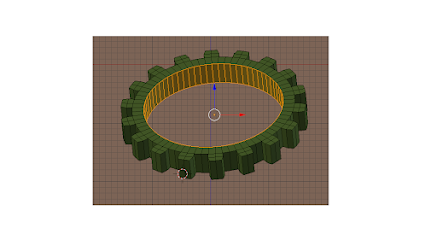
 Let us say we want to add  faces between the two edge loops in the gear shown in image 1 to get a final output as shown in image 2. We can use the Bridge Edge loops option to get this result.

STEPS
1. In Image -1, select the gear and go to edit mode. Set selection to Edge selection mode. Select an edge on one of the circular edge. Then on the 3D header, click on "Select" and then click on "Edge Loop". The complete circular edge will be selected.


                                                                Image-1

 
2. Holding Shift key down, click on an edge on the second circular edge, Click on "Select" and then click on "Edge Loop". Now both the circular edges would be selected.
3. Now on 3D header click on "Mesh" and then click on "Edge" and select "Bridge Edge Loop" in the popup menu. Now faces will be added between the two circular edges as shown in Image -2.


                                                                Image -2

 
4. Note this option  works only  if the two edges are part of a single object.

Thursday, 16 September 2021

DECIMATE MODIFIER

  Let us say we created a mesh object, but ended up with a lot more number of vertices than you think is the optimal number. To maintain the overall shape and still reduce the vertex count, decimate modifier can be used. The way to use it is explained below:

  Add a Monkey object and change to edit mode. In the info editor header the number of vertices is shown as 507. Change to solid mode. Having the monkey object selected, go to Properties Editor and click on the Modifier icon(Spanner), then click on Add modifier button.  In the drop down menu under "Generate" click on "Decimate". Under the "Collapse-Un-Subdivide-Planar" buttons,  "Ratio    1.0000" is visible  which is a slider control. Click LMB and drag to change the value from 1.0000 to say 0.700. Next click on Apply button. The number of vertices would have reduced to 360.

  As you reduce the ratio value, the vertex count will reduce, but beyond a point the details of the mesh shape will tend to be lost.


Tuesday, 14 September 2021

TO ANIMATE THE COLOR (DIFFUSE) SETTING OF THE CUBE


Blender 2.79b
Open a new Blender file with the default objects - A Cube, Camera and lamp.Set up the objects as per details given below.
Settings:

1. Cube- location 0,0,0, rotation to 0,0,0.
2. Camera- location, 7.5,-6.5,5.5 ,rotation 65,0,45.
3. Lamp- location  4,1,6 , rotation  40,0,110. on the  Properties Editor window set lamp  energy to 10 and   diffuse (RGB) value to 1,1,1.
4. View - Camera view by pressing 0 on the Numpad.
5. Viewport shading - Rendered - In the 3D window header.
6. Time line editor window-Set cursor (green line) at frame number 1. End frame to 100.

In 3D window select the Cube, then in  Properties Editor window,click on Material Properties icon, and then, in the Diffuse panel, click LMB on the color band which opens up a color selection wheel. Set the RGB value to 0,1,0.Click RMB a popup  menu will appear. Click on Insert keyframe. An yellow line appears at frame one indicating that a key frame is inserted. Now move the cursor to frame 100. Change the Diffuse color setting  to 0,0,1. Click RMB on the color band,in the popup menu , click on insert keyframe, a key frame will be inserted at frame 100. Now save the file.Position the cursor at frame number 1.

On the info Editor header, Click on "Render" and then click on "Render Animation". The animation will  be rendered. Once the rendering is done, click on "Render" once again and click on Play Animation. The light color of the Lamp will change from Red to Blue, as the cursor moves from frame 1 to 100.

 This effect will be visible with the color of the cube  changing from Green to Blue  due to the diffuse color being animated.

TO ANIMATE THE COLOR SETTING OF A LAMP

 TO ANIMATE THE COLOR SETTING OF A LAMP

Blender 2.79b
Open a new Blender file with the default objects - A Cube, Camera and lamp.Set up the objects as per details given below.
Settings:

1. Cube- location 0,0,0, rotation to 0,0,0.
2. Camera- location, 7.5,-6.5,5.5 ,rotation 65,0,45.
3. Lamp- location  4,1,6 , rotation  40,0,110. on the  Properties Editor window set lamp  energy to 10 and   diffuse (RGB) value to 1,0,0.
4. View - Camera view by pressing 0 on the Numpad.
5. Viewport shading - Rendered - In the 3D window header.
6. Time line editor window-Set cursor (green line) at frame number 1. End frame to 100.


In 3D window select the Lamp, then in  Properties Editor window,click on the Lamp icon, and then, below the Point lamp button, click RMB on the Red color band which opens up a pop-up menu. Click on Insert keyframe. An yellow line appears at frame one indicating that a key frame is inserted. Now move the cursor to frame 100. Change the color setting of the lamp to 0,0,1. Click RMB on the color band,in the popup menu , click on insert keyframe, a key frame will be inserted at frame 100. Now save the file.Position the cursor at frame number 1.

On the info Editor header, Click on "Render" and then click on "Render Animation". The animation will  be rendered. Once the rendering is done, click on "Render" once again and click on Play Animation. The light color of the Lamp will change from Red to Blue, as the cursor moves from frame 1 to 100.
This effect will be visible with the color of the cube  changing from Red to Blue due to animation of color setting of the Lamp.


Monday, 26 July 2021

QUERY ON BLENDER BASICS

 1. Do you have any query on Blender Basics ? Do you want want  to know how to do some thing in Blender ?

Send a mail to iblnd300@gmail.com.


2. We also conduct online classes on Blender Basics. Get in touch for more details.

Sunday, 25 July 2021

ADD-ON : NODE WRANGLER

                                     ADD-ON:  NODE WRANGLER


INTRODUCTION

Node Wrangler Add-on is an add-on officially bundled with the Blender software. It has to be enabled as explained under the head Add-on in this blog.
Node Wrangler is used to add material and texture to any object designed in Blender using PBR (Physically Based Rendering) image data which gives a near real world material output of the rendered image.

DOWNLOAD
PBR image files can be downloaded from some websites, for free at no cost. Paid versions are also available.These files which are compatible to Blender, are to be downloaded. Normally it  comes as a zipped file, for each texture, from which the PBR files must be extracted and stored in  a distinctly named folder.The extracted files contain color, displacement, roughness, normal, albedo and other geometric data of the image.

APPLYING PBR IMAGE TEXTURE TO AN OBJECT
1. The  UV maps of the 3D model must be subdivided and unwrapped first before applying PBR textures.
2. Split the work area into three : 3d, View Port shading and Node Editor. Select the object in 3D window. Set the Render engine to Cycles.Go to Node editor and check Use nodes and then New. A Diffuse node connected to the output node will be added to this window. Delete the Diffuse node and add a Principled BSDF node and connect it to the Output node(Green to Green socket).

3. With the Principled BSDF node selected, press Ctrl+Shift+T. Now you must open the folder where the PBR files are saved and select all the files for a particular texture and click on "Principled Texture setup" Button at the top right corner.

4. A node tree is setup connecting all the selected files to the principled BSDF node. Save your  file. Adjust the settings in the different nodes and study its effect on the final result shown in the viewport shading window which must be set to "Rendered".


Wednesday, 7 April 2021

LIMIT LOCATION/ROTATION/SCALE/DISTANCE CONSTRAINT

Three separate constraints to limit location, rotation and scale are provided to limit the respective transformation of an object. All these three constraints do not require a target object. The limiting parameter is set for the source/owner object. 

Let us consider the limit location constraint. The lower and upper limit can be set for each axis- X,Y and Z separately or in combination like X and Y, Y and Z or Z and X or X ,Y and Z. Setting an upper limit of 5 along X axis would limit the movement of the object along  X axis up to  5 units. The distance is considered from the initial position of the object origin  to the limiting value  set by us for the origin, of the source object. Setting the minimum and maximum value to zero along any axis will lock the movement of the object along that axis.

Clicking the For transform option will limit the movement with in the set minimum and maximum value, which we can see in the location parameters displayed in the properties  panel. By unchecking the Transform option, you will see that the object is visually limited to move within the set parameters, but the actual value can go beyond the set limits. This again you can see under the location parameter.

Setting the Influence value to zero will make the limits set to become in-effective, setting it to 1 will make it effective on a100% basis. If the maximum value is set to 5, the object movement will be limited to 5. If influence is set to 0.5 and maximum value is set to 6, the object will be limited up to 3 units.

Similar logic is applicable to limit Rotation and Scale constraint.

Limit Distance constraint requires a target object with respect to which the limit operates.    


Thursday, 3 December 2020

ANIMATION

 ANIMATION-2

ADDITIONAL FEATURES


 Here we shall learn about some additional  features of animation in Blender. When we want to animate a character(say a Cube), apart from changing its location, its angle of rotation and size(scaling) can also be animated. Again combinations like location and rotation, location and size,rotation and size or all three location-rotation-scale can be varied. Further these changes can be effected on all three axes - X,Y and Z.
 Further not only the objects in Blender like the Cube, Cylinder,Cone, UVSphere can be animated, the Camera and Lights can also be animated .  Further, the different shades of colour of an object or the brightness level can also be animated.  
 If there are more than one object in the 3D Screen, when we animate, we must set key frames for each Object. Again when the movement of the object is complex, (when we make a robot to walk like a man) then the number of keyframes would also increase very fast. This can be a very daunting task. To simplify the keyframing process and to speed it up, we can use Auto keyframing.


BLENDER ANIMATION

 ANIMATION 1 -INTRO

The word "Animation" is derived from the word "Animate" , which means to make an object come alive or to move like a living being. Cartoon characters are a good example of animation where the characters are made to walk, jump,slide,laugh or do  any other motion.


ANIMATION CONCEPT

Let us understand the basic concept of animation. Look at the image of an arrow facing upwards in Fig-1. 


                                                      Fig-1


We want this arrow to smoothly turn to the horizontal position as shown in Fig-2.


 Fig-2

To animate this arrow, we draw images of the arrow at in-between positions as shown in Fig-3.


                                                                         Fig-3

 The whole set of image, from beginning to end,  would then be as shown below in Fig-4.


                                               Fig-4


When we animate these images the computer will generate images for all in-between positions and show all the images in  sequence. The arrow will appear to turn smoothly from Vertical to Horizontal position as shown in the video, whose link is given below:

https://drive.google.com/file/d/1krmBTsjkgH9fgMNc59FPzZn7MZxIsxkb/view?usp=sharing


 In animation, one basic idea we must know is that when a sequence of images are run quickly at a minimum rate of 24 images per second the human eye sees the image movement  as a continues movement. This   idea is used in all animation, videos and movies.

 In Blender each of this image, where some change is made, is called  a Keyframe. We must set the key frames in Blender. In the Arrow animation example we discussed above, we have set four keyframes.  When we animate, Blender generates all the intermediate frames.

Now we shall learn to animate a Cube in Blender. The steps are given below:

1. Open Blender and then a new file and add an object(Cube)  at x,y location(0,0) in the Top view(Press Numpad 7).
2. In the Timeline window as shown below, set the frame number to 1.


2. Position the cursor in 3D window and press "I" key. In the "Insert keyframe Menu" panel which opens, select "Location".


An yellow line will appear in the Timeline window which indicates that a key frame is inserted.


3. Next set the frame number to 125 in the Timeline window as shown below. 


In the 3D window move the cube to x,y location (5,5). Hit "I" key, then select Location in the "Insert Keyframe Menu" panel. An yellow line will appear in the time line window which indicates that a key frame is inserted at frame 125.


4. Next set the frame number to 250 in the Timeline window as shown below.


In the 3D window move the cube to x,y location (10,10). Hit "I" key, then select Location in the "Insert Keyframe Menu" panel. An yellow line will appear in the time line window which indicates that a key frame is inserted at frame 250.
5. Now set the frame number to 1 by pressing |<< key in the TimeLine window. This can also be done by entering 1 in the window as shown in the image above. To play the animation, press > key.
6. Save the Blender file.


Wednesday, 25 November 2020

UNITS IN BLENDER

 UNITS IN BLENDER(Blender Version : 2.79b)

 Units of measure in  Blender are as default set as Blender units. When we open the default screen and then press "N" key to open the properties window where we can see the dimension of the default cube is 2 units along all X,Y and Z axis. These units are defined as Blender units which serves as a general  unit of measure to set dimensions of any object or to compare their dimensions.
 

 Measuring units in Blender can also be set as mm(millimetre), cm(centimetre), m(metre) or as inch, feet, yard etc. To set the units with these units, the procedure is as follows:

 In the Properties window click on the "scene" BUTTON.(the third button from the left). You will see the drop down panel with heading "Units" and the button marked "None" which  would be highlighted with Blue colour. Click on Metric. Now move to 3D window and make sure you have added an object(let us say a Cube). Now hit "N" key to open the panel which would display the location, scale and dimension of the cube. Under Dimension, enter 10cm for x,y, and z dimension. The background  grid would change accordingly and the unit as  cm will be displayed at the top left corner of the 3D window.

 If you select the option "Imperial", then you can set the unit as inches or feet.


Tuesday, 24 November 2020

BOOLEAN MODIFIER

 BOOLEAN MODIFIER

 Boolean Modifier can be used to do the following three operations on an object- ie, union, intersect or difference.
 

  When we apply  an union operation then the end result is the combined shape of the two objects. Intersection is the the shape of the two objects where they commonly intersect. In case of difference, it the shape of the second object is removed from the first object. As an example if you consider a cube and a cylinder. when you do an union operation it will be the combined shape of the two objects. If you do intersection then it will be length of the cylinder which is intersecting with the cube will be the result. In case of difference the end result will be a cube in which the volume up to which the cylinder intersects with the cube is removed as if a hole is drilled in the cube body.

 To apply the Boolean Modifier, the steps are as follows: In the 3D window, add a Cube scale it 3 time along the X and Y axis. Add a cylinder and scale it 5 times along Z axis only.
To do the union operation, locate the Cube a convenient location, the position the cylinder on the Cube such that about 3 units length of the cylinder is inserted into the Cube.

 Now go to the Properties window and click on the spanner icon to open  the Add Modifier drop down menu. Click on "Add Modifier" . Under Generate heading,click on Boolean, under operation select Union. Select the Cube in the 3D panel, under Object click inside the window where you see an ink dropper icon. Select the cylinder. Then click on the Apply
button. Click on the cylinder to select it and drag it away. You will the Cube and cylinder joined as a single object.

 Follow the same procedure for intersect or difference. Corresponding to this operation the setting under "Operation" should be selected as Intersect or Difference.Then click on Apply. After the operation move the cylinder away to see the end result.

NOTE: When you are positioning the two object in the 3D window, under "View Port shading"  select wire frame. This will give wire frame view of both the objects.This view option is preferable over the solid view option.


Monday, 23 November 2020

ARRAY MODIFIER

 TO CREATE MULTIPLE OBJECTS OF THE SAME TYPE(BLENDER 2.79b)

 If you want to create, let us say 10 cubes of the same size , placed side by side with some spacing between the cubes Array modifier can be used.
 

  First open the 3D window and a cube.To active the Array modifier, go to the Properties window and clip on the spanner icon.A window with a  heading "Add Modifier" will appear. It has a drop down menu with a number of modifier options. Under the Generate heading click on "Array" to open the Array modifier option. In the window which opens, set count to 10 and under the Relative option, against x axis set it to 1.1 . Then click on Apply button to create an Array of 10 cubes.

 You can try out different settings by varying the count setting, and offset settings. Similarly set the offset along Y or Z axis and  see the result.For more details on Array modifier, see some video tutorial on the subject.

 Once the array is created, go to edit mode and hit "P" key and then click on Separate  by loose parts. Then go to object mode,select all the cubes and click on Ctrl+Shift+Alt+C to move the origin to the centre of each cube. Now each cube can be moved separately. Before you did this, all the cubes would move together.

Array modifier can be used to create a row of cubes(any object), which we may define as 1X5 for a row of 5 cubes in one row. Two dimension layout of cubes can also be created, which we may define as 5x5 and three dimension can be defined as 5x5x5.

To create a 2D array of say 5x5, first create an array of 5 cubes. Select all the 5 cubes, again open Array modifier set the count to 5 and the offset against y axis as 1.1 and click on Apply button.

To create a 3D array, select all the 25 cubes created above, set count to 5 and the offset against Z axis to 1.1 and click on Apply button.


ROUND EDGES- BEVEL TOOL

Blender version 3.6 To make any edge to be rounded smoothly, we can use the bevel tool in Edit Mode. Look at the cube in Image 1 where all t...