Search This Blog

Friday 26 March 2021

TRACK TO CONSTRAINT


When we talk about constraints we talk about a source/owner and the target object. Constraint is applied to the source object. The source object, when it has to pickup  the control parameters from another object, then a target object is added. Some constraints of this type are transformation constraint, action constraint, copy location/rotation/scale constraint. Some  constraints which do not require a target object are limit location, limit distance, limit rotation and so on.

 Track to constraint, in simple terms means  a "Look at"  sort of constraint. When you have an object say a monkey(target) and the camera (source) on which the constraint is applied, the camera is set to face the monkey, irrespective of the movement or rotation of the Monkey or the camera. If the "Up" and "To" axis setting is the same, the constraint will not work. The influence setting can vary from 0 to 1. Zero means no effect, 1 means maximum effect.


The three images above shows how the Camera is always facing the Monkey.


The settings to activate the Track-to constraint is shown above. Some other examples of using this constraint are given below:

1. Let us say a ball is bouncing across the ground and the player's eye balls are continuously following the ball, then the constraint  is applied to the eye ball with the ball as the target.

2. Let us say a singer is moving around on the stage and a focus light is set such that the light beam always follows the singer, then the target will be the  singer and the constraint will be applied on the light(source/owner).

Experiment with the settings to get a hang of how it works.


Wednesday 24 March 2021

CONSTRAINTS

 Constraints are a way to control an object’s  location, rotation or scale. Constraints can be used on objects or bones.Constraints are  mainly  used in animation. It can also be used on objects for controlling in a static sense. While constraints are used on the object as a whole it can also be used to control a vertex group or a bone part.
 

To apply a constraint to an object(or bone), first select it.

Constraints can be activated from the Properties panel  by clicking on the button having two chain links as its image icon. Hovering the cursor over this icon will display its name.

 When you have an object in the 3D window, constraints can be  activated by going to the header bar which is below the 3D windows, clicking on Object ->Constraints-> "Add constraints with target".  Keyboard shortcut for this is Shift+Ctrl+C. This will open the constraints menu panel. Here click on the particular constraint. This will open the particular constraint's menu window where required setting should be made to  activate the constraint. 

 More than one constraint can be applied to an object which is known as cascading constraints. All the constraints from top to be one below till the last one will have its effect on the object. 

 A constraint when applied to an object may be temporarily deactivated by clicking on the eye icon in the constraint window, to closing it. 

 Further the influence setting which has a value varying from 0 to 1 can be animated. Setting the influence value to zero will also deactivate  constraint.


Sunday 21 March 2021

TO SHIFT ORIGIN OF AN OBJECT TO ANY POINT


Origin of an object can be shifted  to any point on the object or outside it.


TO SHIFT ORIGIN OF AN OBJECT TO ANY POINT ON THE OBJECT

 Follow the steps given below:

1 Select the object and go to edit mode by pressing Tab key.

2. If all the vertices are selected, press  "A" key to de select all vertices.

3. Click on the desired vertex on which the Origin needs to be positioned and go to Mesh-> Snap->Cursor to selection.

4. Press Tab key to go to object mode. Now press Object->Transform-> Origin to 3D Cursor.

TO SHIFT ORIGIN OF AN OBJECT TO ANY POINT OUTSIDE THE OBJECT.

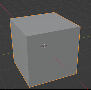
1. Let us consider a Cube for this example.

2. Select Cube and press Tab key to go to  Edit mode. 

3. Select all the vertices, including the ones hidden from your direct view.

4. Assume that we want the Origin to be 3 Blender units away from the geometric Centre of the cubes. Press G-> X-> 3 and hit Enter key.


Thursday 18 March 2021

ADD ONS

 Add-ons are scripts which are written to be used with Blender to achieve additional or special functionalities which are not coming with the core -Blender software.  Add-ons are grouped into Official, Community or Testing.

1. Official  add-ons are  provided with Blender, but needs to be enabled.

2. Add-ons which come under the Community are developed by the Blender community members. These add-ons generally needs to be downloaded from the web, and installed and then enabled to make it usable.

3. Add-ons coming under the Testing group are mostly developed by community members by still under test for performance with out any glitch.

To access Add-on set up in Blender follow the following path. File->User Preferences->   Add-Ons and enable the desired Add-on in the list provided below and click on Save User settings to save the  enable setting of the add-on, just done by you.


Thursday 11 March 2021

TO COPY NODE TREE FROM ONE OBJECT TO ANOTHER.


Assume that you you have made a node tree to set up a new material for an object(Let us say an UV Sphere). Now you add  another object (let us say a Cube). To copy the node tree from UVSphere to the Cube follow these simple steps:


1. Select the UVSphere. In the node editor set up a simple material node tree and save it. Now select all the nodes using Box select option. To copy these node tree to clip board click on the first floppy disk (like icon in light yellow color on the menu bar of the node editor.


2. Select the Cube,click on new material and click on new. You will see a Diffuse BSDF node connected to the Material Output node.Click inside the node editor window using LMB. Now click on the floppy disk icon on the right side. The node tree of the UVSphere will be pasted here. Select the 3D window  and press Shift+Z to see the rendered view of both objects with the new material. Change in material setting of the nodes of UVSphere does not affect the material settings of the Cube.

Tuesday 23 February 2021

IMAGE BASED LIGHTING (IBL)

  This learning material for Image Based Lighting (IBL) is written as applicable to Blender Version 2.79b. Image based lighting setup  is done using cycles node, with render Engine set to Cycles. Download and keep an HDRI image ready for use as the background Image.


Now the steps are as follows:

1. Set up a basic scene with a Cube  as the main object and a plane below it to serve as the ground. Add material and texture to both the Cube and Plane using cycles nodes. 

2. Change the lamp to Sun and set  strength to 3. Rotate it to direct its light ray on to the Cube.

3. Set the Camera and hit  0 (zero) key in Number pad to go to camera view. Adjust its position and direction to get desires view. 

4. In the properties Panel in the right, select World settings. Go to surface panel and for Surface select Background. 

5. Split the 3D window into three windows. Two at the top and the third one below. The top left window may be used to see the rendered view(Shift+Z), the top right window to see the 3d view and the window opened below may be used as a Node editor. 

6. In the Node Editor window, select World  for World setting. 

7. Add three nodes -  Environment texture, Background node and World Output node from left to right. Connect Color in Environment Node to Color in Background Node and from Background   here to Surface in World Output Node. Now the background would turn to a pink Color in the Rendered view, which indicates that all your node setting are ready for IBL. 

8. In the Environment Texture Node go to Open File option and open the HDRI image file. Now you will be able to see the image on the HDRI image file as the background in your scene. To see the rendered scene, hit Shift+Z in the top left window which we had opened for seeing the rended output.

9. If you want see the rendered image in full screen, first click inside the top left window and then press Shift + Space Bar. To go back to previous view hit Shift+Space bar key again. It toggles between the two view modes.


Thursday 3 December 2020

ANIMATION

 ANIMATION-2

ADDITIONAL FEATURES


 Here we shall learn about some additional  features of animation in Blender. When we want to animate a character(say a Cube), apart from changing its location, its angle of rotation and size(scaling) can also be animated. Again combinations like location and rotation, location and size,rotation and size or all three location-rotation-scale can be varied. Further these changes can be effected on all three axes - X,Y and Z.
 Further not only the objects in Blender like the Cube, Cylinder,Cone, UVSphere can be animated, the Camera and Lights can also be animated .  Further, the different shades of colour of an object or the brightness level can also be animated.  
 If there are more than one object in the 3D Screen, when we animate, we must set key frames for each Object. Again when the movement of the object is complex, (when we make a robot to walk like a man) then the number of keyframes would also increase very fast. This can be a very daunting task. To simplify the keyframing process and to speed it up, we can use Auto keyframing.


ROUND EDGES- BEVEL TOOL

Blender version 3.6 To make any edge to be rounded smoothly, we can use the bevel tool in Edit Mode. Look at the cube in Image 1 where all t...